

 The Fusion Handrail system has been designed with
2.
Secure the newel base connector onto the newel base
using the fixings provided. Repeat steps 1 and 2 for all
newel bases.

3.
Measure and fit the baserail
(this process differs depending on whether you have a
closed or open string staircase, see full fitting
instructions for details.

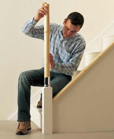
Tip
Put a staircase baluster
in place to check the
handrail height will be
correct before cutting
the post.
4.
After measuring your post to the correct
length, fit and secure the posts in place.
Repeat for all newel posts.
5.
Attach the handrail using the bottom connector.

6.
Fit the handrail to the correct angle using the top
connector on the top post.

7.
Begin fitting the balusters.

Providing the posts have been cut to the correct height
the balusters will not need to be cut.

Make sure you space the balusters correctly before you
start screwing into the timber.
 (For building regulations yu must not be able to pass a 100mm sphere through at any point)
For asthetics keep the spindle spacings even
8.
Begin fitting appropriate landing balustrading.

Jobs Done !

Fusion is available in a veriety of timbers in 2005 and 2006 Beech was very popular but now in 2007 the Oak range is the most popular.

Order online at Tradestars.com
Fusion™ can be fitted to either existing or new newel bases.
To use existing newel bases, these must be fixed centrally to the staircase
string and the front face of the riser concerned (Figs 1 & 2).
Before removing existing newel bases, check that they are non-supporting
or do not form a structural part of the staircase design.
When using Fusion™ your existing newel bases must be a minimum of
82mm x 82mm. If less, face/build up existing bases using suitable facing
material.
These instructions are for a straight flight with return landing.
Existing Bases
Fusion™ stairparts use pre-cut balusters, and all cut-off points are referenced
from the top of the baserail upwards. The system is designed to automatically
compensate for any slight inaccuracies in cutting off the existing newel post.
Before newel bases can be set to the correct height the baserail must be
installed. To do this, lay the baserail on the stair nosings and resting against
the inside faces of the newel bases, mark and cut accordingly taking time to
ensure a clean and accurate cut. Place the baserail on top of the staircase
string, but at this stage, a temporary fix is all that is required ie tacks on
unfinished or masking tape on finished rails (Fig. 3).

Bottom Newel Base
From the line representing the top edge of the baserail mark a line upwards
through the center point of the newel base and where the two lines intersect
measure up 175mm (Fig. 1).
Top Newel Base
The top newel base should be marked out in the same way as the bottom,
but the height should be set at 125mm (Fig. 2).
It is important that existing newel bases are cut off squarely so that the newel
posts are perfectly vertical. Once the bases are cut, trial fit the newel posts
and check with a spirit level. The top of the bases can be sanded level if
required. This will reduce the height of the bases slightly but the newel
assemblies can compensate for this within the connectors. Once the bases
have been levelled they can be chamfered to provide a more pleasing finish.
Newel Base Connectors
Newel base connectors (MMNCS/B) can now be fixed to the newel bases
using the stud and barrel nut supplied. From the top of the newel base on the
centre line previously marked, measure down 125mm. Using a 20mm spade
bit, drill a hole to a depth of 20mm beyond the centre point of the newel base
(Fig. 4). On the top of the newel base find the centre by drawing two diagonal
lines from corner to corner. Using a 13mm spade bit drill to a depth of 125mm.
Note all drill operations should be straight and accurate. Assemble the newel
base connector (MMNCS/B) to newel base (Fig. 5) by locating the barrel nut
and fully inserting the fixing stud. Place the newel base connector over the
fixing stud and tighten nuts using 19mm socket/box spanner making sure
that the connectors are positioned as illustrated (Fig. 6).
Note - in most cases when tightening the base connector to the existing
bases, the retaining ring on the underside of the connector should pull into
the newel base. However depending on the timber type it maybe necessary to
disassemble the connector and chisel a clearance ring of approximately 3mm
wide by 5mm deep allowing the newel base connector to sit flush.
Cut the bottom newel post to a length of 525mm and drill a 25mm diameter
clearance hole at a depth of 25mm to the underside of the post to allow it to
fit over the stud assembly. Fix post to the connector using screws provided
making sure the post is fully inserted. Fix the top post in the same manner
but do not cut the post to length at this stage.
Note – to mark the position of the clearance hole in the newel post, place
newel into base connector, knock gently and then remove post.
New Newel Bases
Fit new newel bases central to the front faces of the staircase risers checking
that they are vertical and at the correct height (Figs 1 & 2).
Note – remember to add the thickness of the baserail when marking the
intersection points as illustrated in (Fig. 3).

Fixing Connectors & Handrails
Fixing the handrails and connectors is best done by two people. To establish
the correct angles of connectors and lengths of handrail, you will need to
assemble two balusters. Fit the baluster brackets to the ends of the staircase
balusters by inserting the screws supplied for a tight fit (Fig. 7).
Note – ensure the baluster brackets are in line with each other by tightening
the screws with the baluster held on two blocks of timber (Fig. 8). The
balusters are pre-cut to length and should not require any modifications.
The bottom connector (MMBCS/B) and top connector (MMTCS/B) are a
two-part assembly. Attach the newel post part of the connectors to the newel
posts. Note – the top newel post connector slides over the top newel post and
should not be permanently fixed at this stage. The handrail part of the bottom
connector should now be attached to the overlong handrail. Offer the handrail
assembly to the newel post connectors and to check that the handrail is
parallel to the baserail and at the correct height, position assembled stair
balusters to the underside of the handrail next to the bottom and top newel
(Fig. 9).
Adjust the height of the top connector by sliding up and down the top post and
check the balusters are vertical using a spirit level. Mark the position of the top
connector to the newel post using a pencil and with the overlong handrail to
the side of the top connector mark and cut the handrail to the required length
(Fig. 10).
Fit the top post connector in place by setting to the previously marked pencil
line and secure the newel post part of the connector using the screws
supplied. It is important that this connector is fixed so that it is in line with the
bottom newel. Fix the handrail connectors to the ends of the handrail and then
fix this assembly to all newel post connectors checking that everything is
vertical and parallel before securing all connector bolts, nuts and screws. You
are now ready to fix the first and last balusters. The last baluster must be fixed
so that it is tight against the handrail connector so as to conform to building
regulations. Position the baluster between the handrail and baserail, check
for vertical and mark the position of the baluster bracket to the baserail with a
pencil. Remove the baluster and fix the baserail to the staircase string using
45mm No. 8 countersink screw. The screw fixing the baserail to the staircase
string should be positioned so that it does not interfere with the baluster
bracket fixing screws. Reposition the baluster and fix to the handrail and
baserail using the screws supplied. Fix the bottom baluster and space so that
the gap between baluster and newel post is no greater than 99mm (Fig. 11).
To space the remaining balusters evenly up the stairs measure the distance
between the spacing marks (notches on the side of the brackets) of the
bottom and top balusters already installed (Fig.11) and divide by 148.5mm.
Round the answer up to the next whole number and divide this whole
number back into your original measurement to give an exact spacing.
Example – 2159mm between bottom and top spacing marks divided by
148.5mm = 14.45, rounded up to 15. 2159mm ÷ 15 = 143.9mm spacing
measurement.
Fix all remaining baluster brackets to balusters using the screws supplied (Fig. 7) ensuring the
brackets are in line using the blocks of wood described previously (Fig. 8). Mark the spacing
between balusters to the baserail either using a pencil and tape measure or by marking and cutting
a piece of timber to the required length. Fix the assembled brackets and balusters to the baserail
first making sure that on every 4th baluster you secret fix the baserail to the staircase string using
45mm No. 8 countersink screws. The top baluster brackets can now be fixed to the underside of
the handrail using a spirit level to check for vertical.
Note – if you have a particularly short flight of stairs you may need to re-space the balusters to
provide a more pleasing effect, remembering at all times to space them no more than 99mm apart.
Assembling Horizontal/Landing Balustrades
Using standard Fusion™ components you will require a minimum 120mm measured from the
centre of the staircase baserail to the centre of the landing baserail for stairs with landings at 180º
to the stairs (Fig. 12).
Cut and mitre the landing baserail to size and place into position on the landing. Do not fix to the
landing floor at this stage (Fig. 12). Fix the landing baluster brackets to the landing balusters.
Place an off-cut of handrail loosely into the landing connector (MMLCS/B). Position one assembled
landing baluster onto the baserail and place the handrail and connector on top of this baluster and
to the side of the top newel to establish the required height of the post. Mark and cut to suit.
Where the landing balustrade ends against the wall, mark the position of the wall connector
(MMWCS/B) on the wall by placing an assembled landing baluster and baluster connectors to offcuts
of baserail and handrail. Mark the position of the wall connector (MMWCS/B) to the wall and
drill and plug to suit.
Note – before drilling and plugging this fixed point check that the landing handrail will be parallel
using a spirit level, if the landing floor is slightly out, reposition the wall connector (MMWCS/B) and
pack the underside of the landing baserail accordingly.
Place an off-cut of handrail to the landing connector (MMLCS/B) and position on the top newel.
Push the landing handrail into the wall connector (MMWCS/B) and offer the horizontal turn
(MMHTRS/B or MMHTLS/B) to where the two handrails meet to establish lengths of cut. Mark
and cut the handrails to the required length. Reposition the landing handrail to the wall connector
(MMWCS/B) and fix horizontal turn (MMHTRS/B or MMHTLS/B) to the other end of this rail. Fix
the short return length of handrail onto the other leg of the horizontal turn (MMHTRS/B or
MMHTLS/B) and the landing connector (MMLCS/B) to the other end of this short return length of
handrail and position over the top newel post (Fig. 13).
Note – before screwing all connectors to rails and top post, we recommend a final check for parallel.
Use a spirit level for the handrail and an assembled baluster/baluster brackets between the rails.
To calculate the exact number of landing balusters either divide the total landing length by 117mm,
which will give a gap of approximately 98mm, or alternatively you may find it aesthetically more
pleasing to space the landing balusters so that they are in line with the staircase balusters. Mark
the position of the baluster brackets to the baserail and secret fix the baserail to the landing
floorboards using 45mm No. 8 countersink screws every 4th baluster.
Assemble all baluster brackets to the ends of the landing balusters by inserting the relevant fixing
screw (63mm No. 8) into the underside of the brackets and tighten (Fig. 7). Ensure that the
brackets are in line with each other as previously described for staircase balusters using two
square blocks of timber (Fig. 8).
Fix all bottom baluster brackets to the baserail using 30mm No. 6 screws and finally secure the top
baluster brackets to the underside of the landing handrail using 30mm No. 6 screws checking for
vertical with a spirit level.